
In the process of PCB design, before wiring, we will generally stack the items we want to design and calculate the impedance according to the information of thickness, substrate, number of layers, etc. After the calculation, the following figure can be generally obtained.
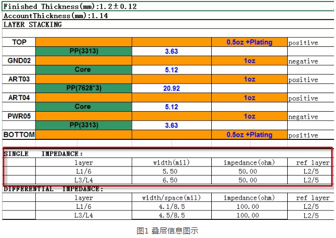
As can be seen from the figure above, the design of the above single-end network is generally controlled by 50 ohms, so many people ask, why is it required to be controlled by 50 ohms instead of 25 ohms or 80 ohms?
First of all, the default choice is 50 ohms, and everyone in the industry accepts that, generally speaking, there must be a standard set by some recognized institution, and people design according to the standard.A large part of electronic technology is from the military, the first technology is used in the military, slowly from military to civilian.In the early days of microwave applications, during world war ii, the choice of impedance was entirely dependent on the need for use, without a standard value.As technology advances, impedance criteria need to be given in order to strike a balance between economy and convenience.
In the United States, the most commonly used catheters are connected by existing rods and pipes. 51.5 ohms is common, but the adapters and converters used are 50-51.5 ohms.To solve these problems for the joint army and navy, an organization called JAN (later DESC) was formed, specifically developed by the MIL, and eventually selected 50 ohms, from which the relevant ducts were manufactured and converted into standards for various cables.
European standard is 60 ohms, not long after, the dominant in the industry, such as hewlett-packard company, under the influence of europeans were changed, so 50 ohm inherited from the eventually become a standard in the industry, has become established, and a variety of cable connection of PCB, for the sake of impedance matching, finally also is according to 50 ohm impedance standards requirements.
Secondly, the formulation of general standards will be based on the PCB production process and design performance, feasibility of a comprehensive consideration.
From the perspective of PCB production and processing technology, it is relatively easy to produce PCB with 50 ohm impedance considering the equipment of most existing PCB manufacturers.It can be seen from the calculation process of impedance that excessively low impedance requires a wide line width and a thin medium or a large dielectric constant.High impedance requires thin linewidth and thick medium or small dielectric constant, which is not conducive to EMI and crosstalk suppression. At the same time, the processing reliability of multilayer plates and from the perspective of mass production will be relatively poor.Control 50ohm impedance in the use of commonly used plate (FR4, etc.), commonly used core plate environment, the production of commonly used plate thickness products (such as 1mm, 1.2mm, etc.), can design the common line width (4~10mil), this sample factory processing is very convenient, the processing equipment requirements are not very high.Considering PCB design, 50 ohms is also the choice after comprehensive consideration.In terms of PCB routing performance, generally low impedance is better. For a transmission line with a given line width, the closer it is to the plane, the corresponding EMI will be reduced and the crosstalk will be reduced accordingly.However, from the perspective of signal full path, the most critical factor needs to be considered, which is the drive capability of the chip. In the early days, most chips could not drive the transmission line with impedance less than 50 ohm, while the transmission line with higher impedance was difficult to realize, so the compromise adopted 50 ohm impedance.
Therefore, 50 ohms is generally chosen as the default value of the control impedance of the single terminal signal.